
How device specs turn into system performance — one pluggable module at a time, Following the signal through a pluggable coherent module: the TFLN modulator, the source, the InP detector, and the test step before assembly.
Open up a pluggable coherent module and you find four things: a stable source of light, a modulator that writes data onto it, a detector that turns it back into a current, and a package that holds all three without letting them interfere with one another. Bandwidth has gone from 100G to 400G and on toward 1.6T while the size and power envelopes have barely moved — because each of those four took a step forward.
This article follows the signal through them in order, and shows how each device-level specification turns into a system-level one.
1. The heart of the transmitter: the IQ modulator
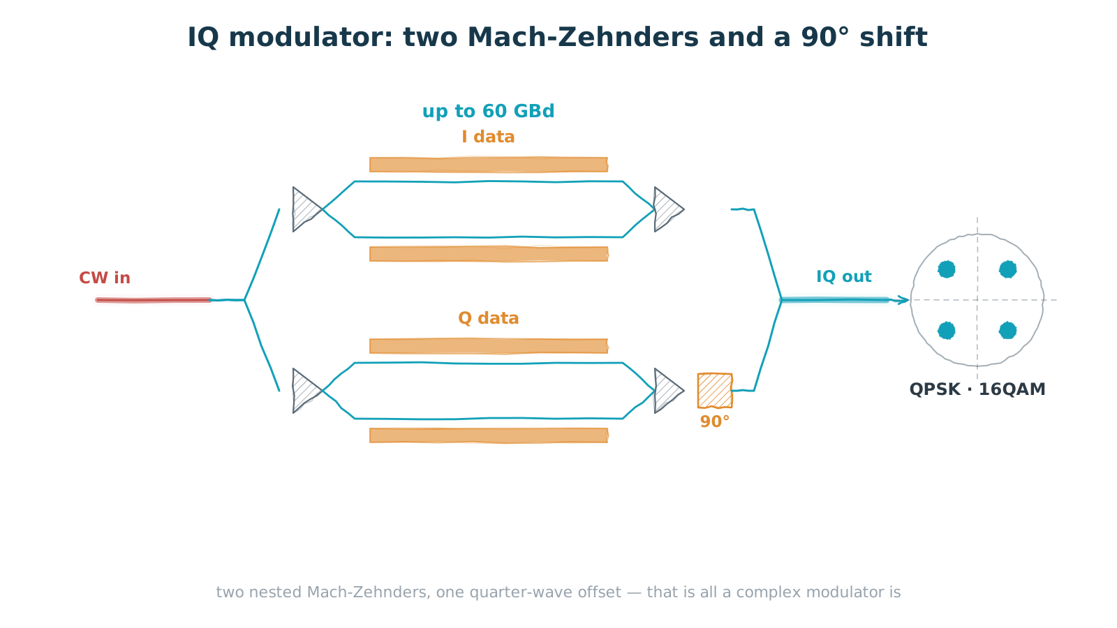
Figure 1 — IQ modulator: two nested Mach-Zehnders plus a 90° shift
each arm modulates one quadrature; together they form a complex constellation
Intensity modulation only varies how bright the light is — one degree of freedom. Coherent modulation wants amplitude and phase, which is two. Mathematically that is complex modulation; physically it is an IQ modulator.
The structure is not complicated. The input splits into two paths, each entering a Mach-Zehnder modulator (MZM), driven by the I and Q data streams respectively. One path gets a 90° phase shift. The two are recombined at the output. Because I and Q are orthogonal, the receiver can separate them again — so the same bandwidth carries a multiple of the bits. QPSK puts two bits on every symbol; 16QAM puts four.
That is why baud rate, not bit rate, is the modulator's headline number. A 60 GBd device is a 100G-class part with QPSK and a 200G-and-up part with 16QAM. It is also why datasheets say "60 GBd" rather than "200G": the latter depends on the modulation format, which is a system choice, not a property of the device.
There is a packaging consequence that is easy to overlook. An IQ modulator contains two child MZMs, each needing a high-speed RF feed, and the chip also has to accept an input fibre and launch an output fibre. If the RF and optical interfaces all crowd onto the same edge, the interconnects fight each other and the module cannot be made short.
2. Folded optics: keeping RF away from the fibre
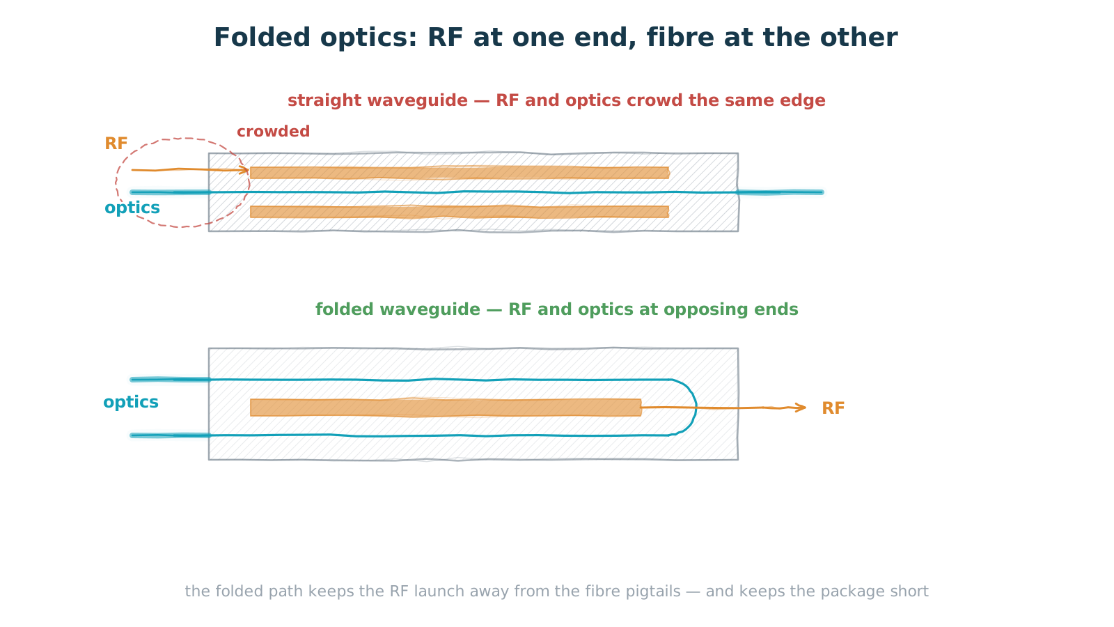
Figure 2 — Straight vs. folded optics: where the RF and optical ports sit
fold the waveguide inside the chip: RF in one end, fibre out the other
The engineering answer is a folded optical path. Turn the waveguide back on itself inside the chip and light enters and leaves at one end, while the travelling-wave electrodes can be fed from the other.
Two things come out of it. First, RF feed integrity: high-speed RF is acutely sensitive to impedance continuity and crosstalk, and keeping it away from fibre pigtails and coupling structures makes the signal much easier to preserve. Second, footprint — a shorter chip gives the module layout room to breathe, which is a hard requirement wherever size and weight are at a premium.
The same reasoning explains why one device shows up in two apparently unrelated applications. On one side, QPSK and QAM encoding for coherent communications; on the other, single-sideband modulation and RF mixing for radio-over-fibre. Both are, at bottom, the same job: putting a high-frequency electrical signal onto light, linearly.
3. Two routes to a source
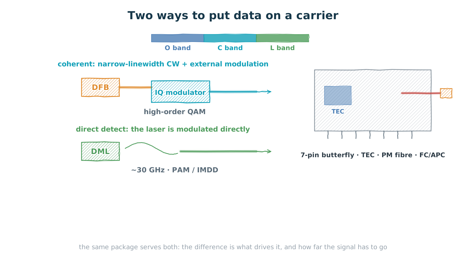
Figure 3 — External modulation for coherent, direct modulation for direct detect
same package family, different drive scheme, different reach
Where does the light come from? Two routes, for two kinds of system.
Coherent systems want a narrow-linewidth, frequency-stable continuous wave, with data written on by a separate IQ modulator. Coherent detection depends on the phase relationship between the local oscillator and the signal, so the source linewidth lands directly in the phase-noise budget — hence narrow-linewidth continuous-wave sources such as DFB lasers.
Direct-detect systems (PAM, IMDD) are not chasing phase. They are chasing cost and power, so they let the laser modulate itself — a directly modulated laser, DML. Dropping the external modulator simplifies the link considerably. The price is that direct modulation bandwidth is limited, on the order of 30 GHz, and the modulation introduces chirp, which interacts with fibre dispersion to cap the reach. That is why DML serves short-reach interconnect inside the data centre.
The two also divide up the spectrum. The O band, around 1310 nm, sits near the fibre's zero-dispersion point and suits direct detection. The C band, around 1550 nm, has the lowest loss and the erbium-doped fibre amplifier to go with it, making it home turf for long haul and coherent systems. The L band extends it, adding channels when capacity gets tight.
At the package level the two share almost everything: a standard butterfly outline, an RF connector, an internal thermoelectric cooler (TEC), an optional isolator, and a polarization-maintaining fibre pigtail with an angled physical-contact connector. The TEC is not optional — laser wavelength drifts with temperature and WDM systems hold wavelength to tight tolerances, so temperature control is a requirement rather than a nicety. Polarization-maintaining fibre likewise serves the applications that care about the state of polarization.
4. The receiver: 110 GHz and balanced detection
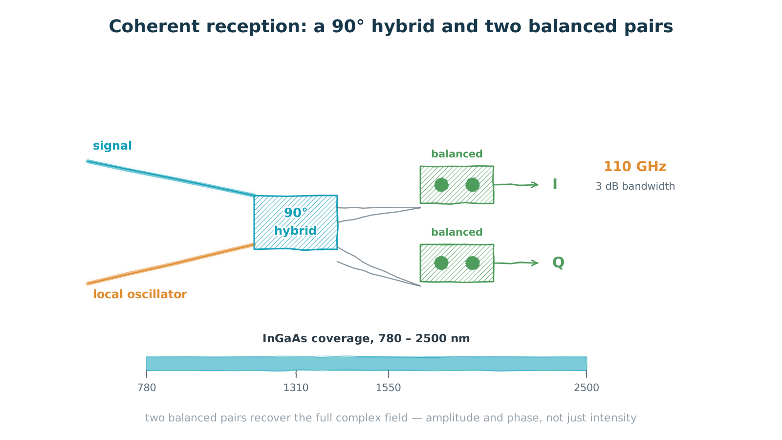
Figure 4 — Coherent reception: a 90° hybrid and two balanced pairs
a local oscillator and differential detection recover the full field
Coherent reception interferes the signal with a local oscillator in a 90° hybrid, splits the result four ways, and feeds each pair into a balanced photodetector to produce the I and Q electrical outputs. The point of balanced detection is subtraction: the two detectors see complementary light, so subtracting cancels the local oscillator's intensity noise — its relative intensity noise — and leaves the signal term.
The bandwidth figure here is the 3 dB bandwidth, and volume parts reach the 110 GHz range. Note that this is not the same quantity as the baud rate in section 1: the detector has to keep up with the electrical bandwidth after mixing, while how fast the system runs also depends on the transimpedance amplifier, the analogue-to-digital converter and the DSP.
On materials, indium phosphide carries high-speed detection. It supports both high-speed, high-power photodetectors and low-noise, high-responsivity InGaAs photodiodes, covering the 780 to 2500 nm short-wave infrared range — which takes in both the O band of datacom and the C band of telecom. That coverage is also why one detector chip family can serve communications and sensing at the same time.
5. One platform, four devices
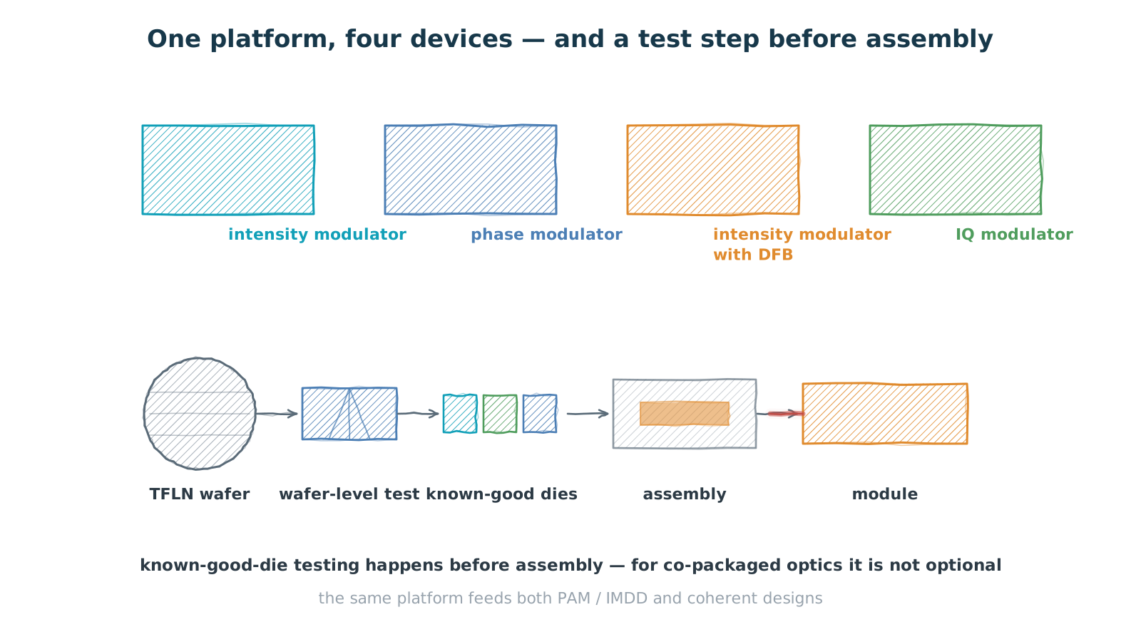
Figure 5 — One platform, four devices, and a wafer-level test step
test on wafer before assembly — mandatory for co-packaged optics
Stepping back, all of the above share a single process platform. The value of thin-film lithium niobate is not only a large electro-optic coefficient. It is that the waveguides can be fabricated monolithically and made compact, and compact waveguides let the electrodes sit closer together. Drive voltage falls and the device gets shorter — lower power and smaller footprint are two consequences of the same geometric change.
One process line therefore yields four devices: an intensity modulator, a phase modulator, an intensity modulator with a DFB laser integrated alongside it, and an IQ modulator. For a system designer that means one platform spans several levels of complexity while the supply chain, the package style and the test methods stay common.
There is one more step between device and module that tends to be underestimated: wafer-level test and known-good die (KGD). The idea is to test and screen on wafer, before dicing and packaging, so that only good dice move downstream. For pluggables that is a cost optimisation. For co-packaged optics it is mandatory — once the optical part of a co-packaged assembly is built, it cannot be reworked, and without KGD there is no yield to speak of.
6. Turning device specs into system specs
Finally, how these device numbers become system numbers. A concrete case: densely integrating a broadband, compact thin-film lithium niobate modulator with a silicon photonics receiver into a pluggable coherent module raised transmission distance by roughly 15% over the previous generation.
That 15% is not one device metric converted directly. It is several paths adding up. Low insertion loss in the modulator lifts the launched optical power. High extinction ratio and clean modulation improve optical signal-to-noise ratio (OSNR). Lower loss on the receive side plus detector responsivity improve receiver sensitivity. Each contributes a decibel or so, and decibels convert to distance — a double-digit percentage in the end.
Which makes a point worth stating plainly: at the system level, loss is often worth more than bandwidth. At a given baud rate, one less decibel of insertion loss is real distance. Another 10 GHz of bandwidth may buy nothing at all, if the link is OSNR-limited rather than bandwidth-limited.
That logic only hardens on the way to 1.6T. Baud rates keep climbing, modulation formats move to higher orders, and the OSNR budget tightens with every step up in order — so loss, extinction ratio and detector sensitivity carry still more of the weight.
Closing: four questions
If you are selecting parts, ask four questions in the order the signal flows.
Modulator: is the baud rate enough, does the drive voltage sit inside your driver's capability, and will the RF and optical interfaces fight each other inside the package?
Source: coherent or direct detect, O band or C band, are temperature control and polarization maintenance actually required?
Detector: what are bandwidth, responsivity and dark current at your highest operating temperature?
Platform: is there wafer-level test, can it supply known-good die, and will the same platform cover your next couple of generations?
Answer those four and the transceiver is largely understood. What is left is fitting them into a housing of fixed dimensions and keeping them out of each other's way.
Bandwidth decides how fast a link can run. Loss decides how far. And inside a fixed faceplate and power budget, the second is usually the harder one to win.